Use case: building scenarios
After opening the Web interface, the scenario panel screen can be opened using the menu at the top left by clicking on the following icon:
![]()
There are roughly three types of scenarios, which are:
- A reference scenario, represented as v0 in Figure 4, that includes the city's simulation results without any interventions. There are no simulation models operating in this scenario;
- A calculation scenario (v1 in figure 4), with active simulation models. In this scenario, the effects of interventions can be calculated interactively;
- A copy of the calculation scenario v1 (v2, v3, and so on), which shows the city's simulation results following a particular set of interventions.
Figure 52 below shows an illustrative example of the available scenarios.
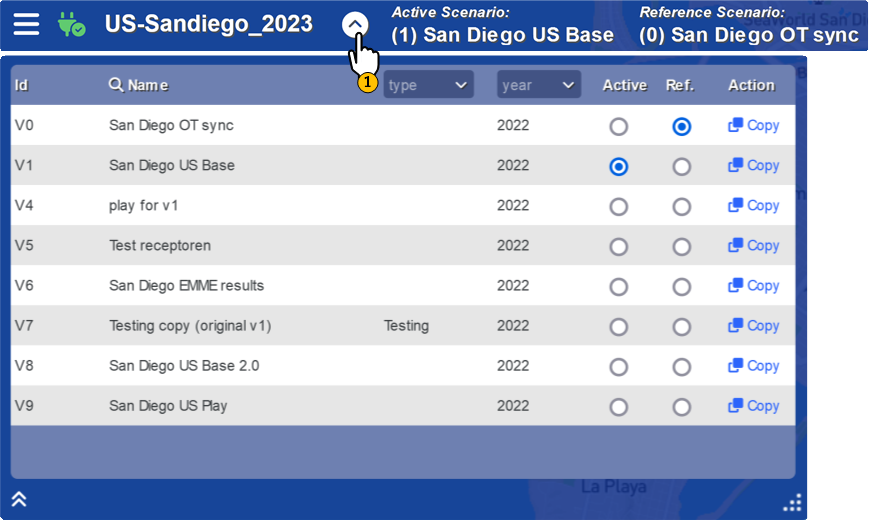 Figure 52: Scenarios.
To build a new scenario, it is important to select the calculation scenario (v1) as the active scenario. This can be done by selecting the 'active' checkbox in the scenario panel (see figure 53).
 Figure 53: Selecting calculation scenario as 'active' scenario.
Open the map and data layers at the bottom left using the icon:
![]()
Then choose the relevant data layer for the intervention, for example the road network for a reduction in the speed limit or the origin and destination points (centroids) for adding new homes (see Figure 54).
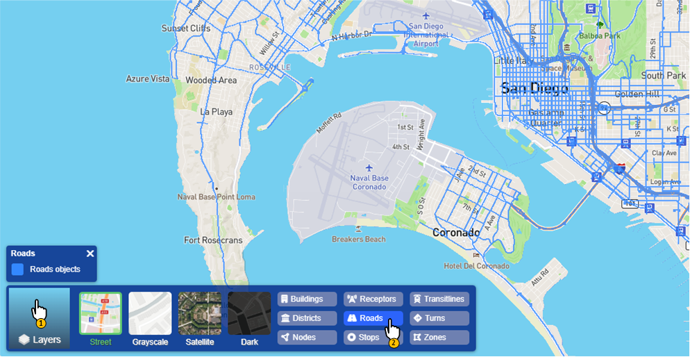 Figure 54: Selecting and visualizing data layers.
After selecting the relevant layer for intervention as depicted in Figure 54, the data element for the intervention can be selected by clicking on the object (see Figure 55). In the case of the road network, each network element has a direction, indicated by the halved pink arrow. In the example in Figure 55, a part of Island Avenue has been selected with traffic driving in an easterly direction. By holding down the Ctrl key on the keyboard, the selection of elements can be expanded.
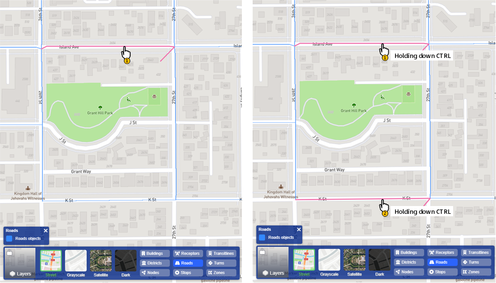 Figure 55: By selecting a road, the selection turns pink (single selection
on the left, multiple selection on the right)
Figure 55: By selecting a road, the selection turns pink (single selection
on the left, multiple selection on the right)
In addition to an individual selection, the selection tools can also be used, as illustrated in Figure 56. These tools consist of selection by means of a polygon, square, circle or based on a query.
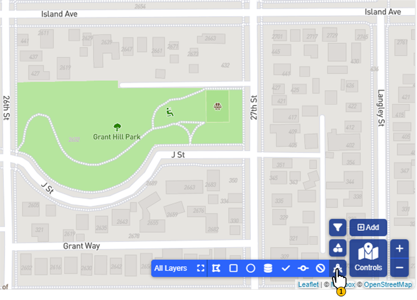 Figure 56: Selection tools.
All elements within the selection, such as the circle in Figure 57, are selected. In the case of the road network, the network elements are selected in both directions. The selection can be adjusted by holding down the Ctrl key on the keyboard, and already selected elements can also be deselected in this way.
(a) Circular selection with Grant Hill Park as the centre
(b) Results of selectionFigure 57: Selection of roads using the circle from the selection tools.
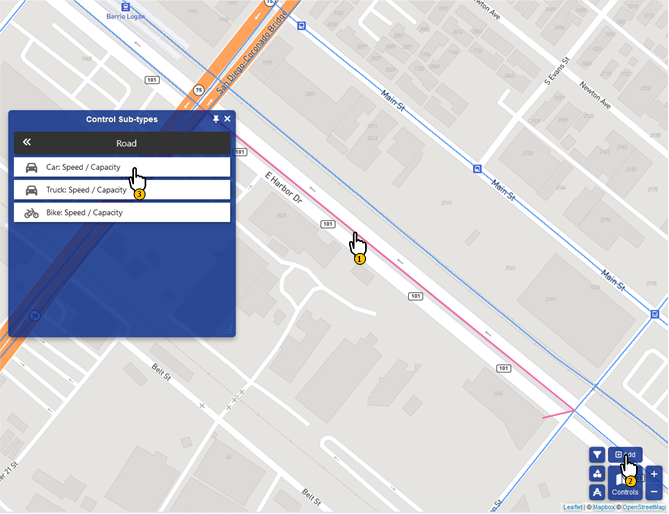
After making the selection, a control can be created. A control is a temporary data adjustment. For example, adjusting the speed of a road for a certain transport mode. To create a control, choose the icon:

There are different types of controls per data element. In the case of roads, it is only one: 'Speed & Capacity'. After choosing the type of control, a window opens for the input of the control properties (see Figure 58). Choose 'Apply' to place the control.
 (a) Selecting the type of control
 (b) Specifying the properties of the control
Figure 58: Creating a 'Speed and Capacity' control on a network element.
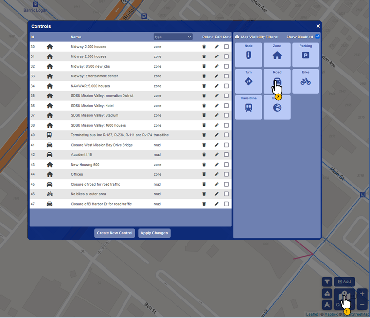
To make the created controls visible in the Web interface, the relevant layer must be enabled in the list of interventions. To do this, select the icon:
![]()
Following that, select the type for visualization (in the case of speed or capacity changes these are 'road' controls), as depicted in Figure 59.
 (a) Making all 'road' controls visible in the Web interface
 (b) Created control becomes visible in the web interface
Figure 59: Activating, adjusting, and removing a control
(closing El Harbor Dr Avenue for road traffic).
By right-clicking on the control it is possible to activate the intervention (option 'enable control'). The control properties can be adjusted in the 'properties of control'. With 'select object(s) of control' the data elements on which the control has an effect become visible (in the above example of closing El Harbor Dr Avenue, this concerns a specific link). 'Remove control' removes the control.
Simulation models respond immediately upon the activation of a control. Activating a set of controls can be done via the list of interventions by checking the boxes (see Figure 60). Following that, select 'Apply Changes' to activate all selected controls.
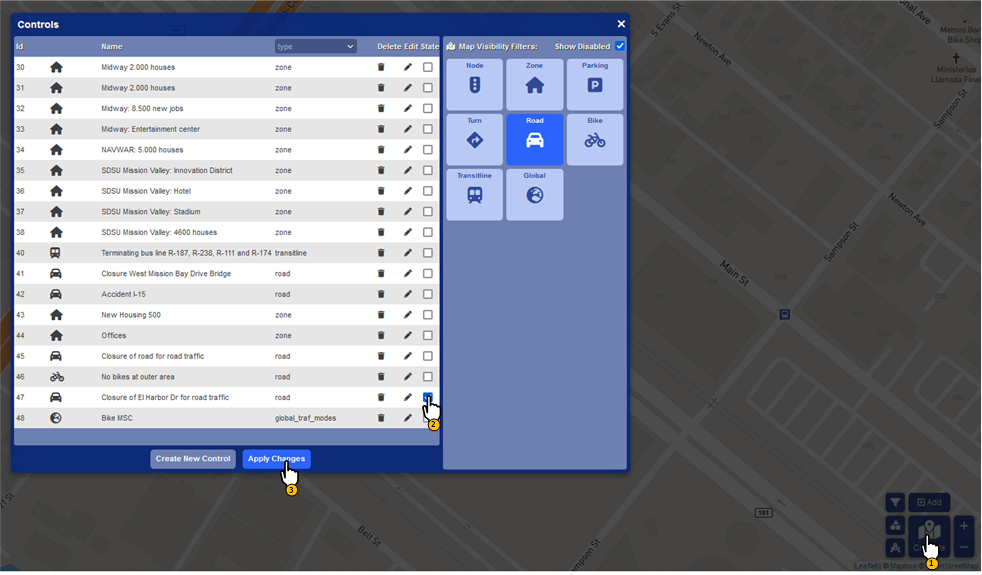 Figure 60: List of controls for activation.
After activating the controls, the various simulation models perform calculations. The status of the models can be requested by clicking on the icon
![]()
Simulation models in the panel (figure 61) with a green background and status 'ready' are enabled and have finished calculating. A grey background with status 'busy...' indicates that the model in question is calculating. A model with a white background is inactive. Note that active models are linked to the selected active scenario (figure 52), in this scenario results will be overwritten.
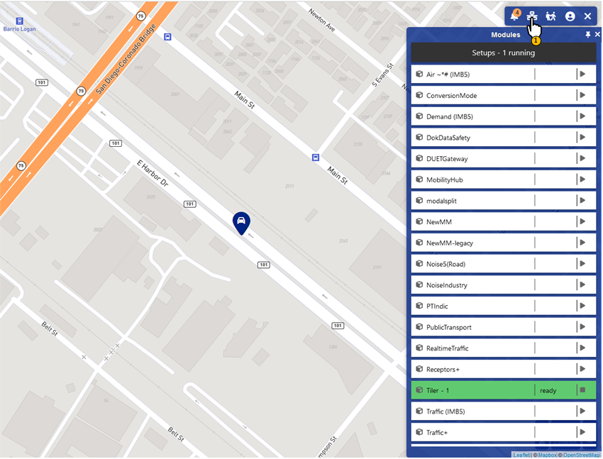 Figure 61: Status of simulation models.
Results can be displayed via the indicators panel (Figure 62). To do this, select the icon:
![]()
Various map layers and graphs can be opened from this panel. Note that the results are shown for the selected scenario (calculation scenario, reference scenario, etc.). After selecting a map layer in the scenario panel, select 'Difference' to compare two scenarios.
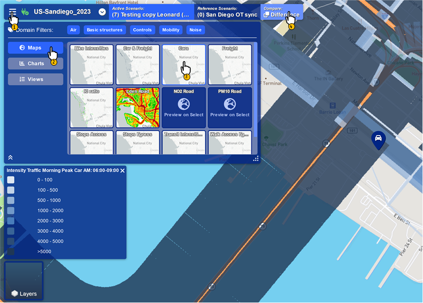 Figure 62: Indicators Panel.